
Negative Phase Sequencing
Negative Phase Sequence (NPS) is a power quality phenomenon that occurs in three-phase electrical systems when the phases are not perfectly balanced. It is a key concern for transmission system operators, equipment manufacturers, and connection engineers. This article explains what NPS is, why it matters, how it is regulated, and how it can be mitigated.
1. Introduction
Understanding NPS has become increasingly important as the number of new connections to the transmission network grows – particularly those related to railway infrastructure, as these are generally 2-phase connections. These connections can introduce unbalanced electrical loads, leading to inefficiencies and operational risks that may compromise the stability and reliability of the power supply, and risk violations of The Grid Code Connection Condition CC.6.1.5.
2. What Is Phase Sequence?
A synchronous generator has a physical rotating mass that produces alternating current (AC). The UK operates a three-phase electricity network at 50 Hz, meaning each generator has three windings spaced approximately 120° apart. As the rotor spins, each winding experiences an induced current in turn, with a 120° phase difference between them.
Phase sequence is the order in which the voltages or EMFs in a three-phase system reach their maximum positive value. In the UK system this is represented as Red (R) – Yellow (Y) – Blue (B), as shown below:

Figure 1: Graph indicating the three-phase RYB phase sequence.
3. Understanding Voltage Unbalance
Dr. Fortescue (1876 – 1936) was a pioneering Canadian electrical engineer. After becoming the first electrical engineering graduate from Queen’s University in Ontario, he spent the majority of his career working for the Westinghouse Electric and Manufacturing Company in the United States. Dr. Fortescue developed the Method of Symmetrical Components (originally titled the Method of Symmetrical Co-Ordinates Applied to the Solution of Polyphase Networks).
To appreciate why this was a massive breakthrough, you have to look at the problem he was trying to solve. Electrical power grids run on three-phase AC electricity. When a power grid is balanced – all three phases have equal voltage and are perfectly spaced out (120 degrees apart for 3-phase). Calculating the behavior of a balanced system is easy; you only have to do the math for one phase, and the other two mirror it perfectly.
However, when something goes wrong, like a tree branch hitting a single power line, causing a short circuit or the network has unbalanced loads – the system becomes unbalanced. Before Fortescue, analyzing an unbalanced three-phase system was a mathematical nightmare because the phases interacted with each other in highly complex, asymmetrical ways.
Fortescue proved a powerful mathematical theorem:
Any unbalanced set of N related phasors can be broken down into N sets of perfectly balanced, symmetrical phasors.
For a standard three-phase power system (comprising phases A, B, and C), Fortescue showed that any messy, unbalanced state can be decomposed into three clean, independent sets of vectors (called “sequence components”):
- Positive Phase Sequence (PPS) — the normal balanced component, rotating R–Y–B.
- Negative Phase Sequence (NPS) — a balanced component rotating in the reverse direction (R–B–Y).
- Zero Phase Sequence (ZPS) — three equal in-phase components with no angular difference.
The sum of these three components equals the resultant phase voltage. A perfectly balanced network contains only PPS, with no NPS or ZPS present. But be aware, there isn’t actually a current or voltage operating in the opposite direction (NPS) or in the same direction (ZPS). These are theoretical and are just a way we use to explain the real world.

Figure 2: Theoretical components of each phase — PPS, NPS, and ZPS.
NPS and ZPS only appear under certain conditions. NPS arises whenever there is phase asymmetry — when the three phases are not equal in magnitude or do not maintain 120° phase angles between them. ZPS appears only during faults involving an earth connection. When phases are balanced, only PPS exists and no return current flows.
The primary sources of NPS in the transmission system are unbalanced loads and impedance imbalances in the network. The England and Wales (E&W) transmission system consists predominantly of un-transposed double-circuit overhead lines (OHLs), which inherently generate some degree of NPS. The largest single contributor to NPS for Electricity Transmission is railway traction connections.
4. Impact of NPS on the Electrical Grid
NPS can have significant detrimental effects on electrical equipment across the grid. The NPS voltage component drives NPS currents through the transmission system and into connected machines, causing a range of problems:
- Generators: NPS causes heating and mechanical stresses, producing torque and vibration that adversely affect the lifespan of generators.
- Motors: NPS leads to overheating. The unbalanced current produces a negative sequence current that creates a rotating magnetic field in the rotor air gap opposing the rotor’s rotation, causing mechanical stress.
- Transformers: Variations in losses across each phase result in elevated hotspot temperatures.
- System stability: Significant NPS currents can destabilise the network, potentially leading to voltage instability, voltage collapse, or even blackouts.
- Protection systems: NPS can cause maloperation of protective devices.
- Power quality: NPS can generate harmonics within the system, which may overload associated filters.
Real-World Case Study
During inspections of GE steam-turbine generators between 1995 and 2001, engineers discovered serious mechanical damage linked to NPS exposure. Three units were found with cracked generator-rotor teeth; in two cases the rotors had experienced in-service NPS events, with arc strikes found on internal rotor components. Under unbalanced conditions, NPS currents in the stator created a backward-rotating air-gap flux inducing current in rotor surfaces and damper paths, causing rapid localised heating. This case study underlines how damaging NPS can be to rotating plant.
5. Regulatory Framework (UK): The Grid Code and NPS
The Grid Code sets out the limits for phase voltage unbalance (NPS) in the UK transmission system under Connection Condition CC.6.1.5:
Voltages above 150 kV (England and Wales): The weekly 95th percentile of phase voltage unbalance must remain below 1.5%.
Voltages at 150 kV and below: The weekly 95th percentile must remain below 2% across Great Britain.
Phase voltage unbalance is measured as the ratio of the RMS of the NPS voltage to the RMS of the PPS voltage, based on 10-minute average values in accordance with IEC 61000-4-30. This is known as the Unbalance Factor (UBF), also referred to as Vnps%:
The 1.5% limit applies to all planned outages on the transmission system (e.g. a single planned circuit or transformer outage), consistent with Chapter 2 of the SQSS. Further secured planned or fault events described in Chapter 5 of the SQSS are assessed against the 2% limit, as these events occur rarely and for short durations.
A review by NESO (F. Ghassemi and M. Perry) previously proposed increasing the transmission limit from 1% to 1.5%, noting that overly tight limits increase costs for network operators and consumers without a meaningful improvement in equipment reliability. On the result of this report, the limit was increased to 1.5%.
6. NPS Contributions from Overhead Lines (OHLs)
One of the main sources of unbalance in the transmission system is un-transposed OHLs. A perfectly transposed line would have equal phase impedances across all three (or six, for double-circuit) conductors. In practice, the E&W transmission system is almost entirely un-transposed.
Because the three-phase conductors are not located in the same physical position relative to one another, their self-impedances and mutual inductances differ slightly. These differences result in unequal impedances per phase, which introduces both NPS and ZPS into the system. The magnitude of NPS voltage introduced by any OHL fluctuates with power flows — contraflows and flow mismatches between parallel circuits amplify the effect.

Figure 3: Generator contra-flow (left) and demand flow mismatch (right) — both conditions increase NPS contributions from OHLs.
7. Solutions to NPS on the Transmission System
Several technical solutions are available to mitigate NPS, each with different effectiveness, cost, and practicality. The transmission licence requires that the network be designed as efficiently and economically as possible, so each option must be evaluated critically. Low-cost operational measures are modelled first; structural changes are justified only where simpler options prove insufficient.
Specify Appropriate Phase Pair for Unbalanced Load
The cheapest and simplest method for connections only connecting to 2-phases. By selecting which pair of phases to connect an unbalanced load (such as a railway) to, NPS can be minimised at the point of connection. It does not remove the root cause of imbalance, but reduces its impact.
Alter Phasing Arrangements of Circuits
Changing the phasing at pylons or along OHLs redistributes the effects of mutual inductance and can significantly reduce system-wide imbalances. This is effective where multiple overhead lines run in parallel, but is moderately costly and requires careful system studies and sometimes physical rearrangement of conductors.
Alter Turn-Ins to Tee-Points
Tee-points can reduce system impedance and spread current more evenly across the network. However, effectiveness is highly dependent on local network topology — in some cases (particularly where only generation is connected) it may worsen thermal loading and increase NPS.

Figure 4: Graphic depicting tee-points (left) and turn-ins (right).
Upgrade Tee-Points to Full Substations
Full substations provide additional parallel current paths, naturally balancing loads. Highly effective, but involves substantial capital investment, land acquisition, and planning. Appropriate only where long-term demand growth justifies the cost.
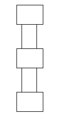
Figure 5: Graphic depicting upgrade from tee-points to full substations.
Introduce a Phase Balancer
Phase balancers redistribute power evenly across all three phases, directly targeting the source of NPS. Technically sound but equipment costs and ongoing maintenance can be high. Often used where persistent imbalances cannot be resolved by simpler methods.
Build New Circuits to Increase Fault Level
Adding new circuits increases network strength, reduces system impedance, and improves resilience to unbalances. The most capital-intensive option, with long lead times. Usually only considered where multiple future reinforcements are planned or where security of supply is critical.
8. The Purpose of an NPS Assessment
During the design of any new transmission circuit or network topology change, NPS voltage studies should be completed to check for compliance with the Grid Code limits and identify any required mitigation.
The credible worst-case network conditions should be assessed – typically a condition of relatively low fault level combined with high line flows. For most network areas, a summer maximum condition is the most onerous. Any non-compliance identifies where NPS voltage levels may exceed Grid Code limits.
Key Risk & Benefit Summary
Primary risk: NPS voltage generates torque that opposes generator shaft rotation, causing vibrations that shorten asset lifespan.
Key benefit: Conducting NPS studies to guide phase ordering for new substations and unbalanced connections does not increase connection costs and can effectively mitigate risks in most situations.
9. Mathematical Foundations of NPS
The mathematical basis of NPS analysis was established by Dr. C. L. Fortescue, whose theory of symmetrical components allows any set of unbalanced voltages or currents to be resolved into three sets of symmetrical, balanced phasors – PPS, NPS, and ZPS.
Single Three-Phase Circuit
Voltage
This method applies when only a single circuit with three phases is available. The subscripts 1, 2, and 0 denote PPS, NPS, and ZPS respectively. So the denotation Vc1 means PPS Voltage of phase C, Va2 denotes NPS Voltage of phase A etc…

Figure 6: Symmetrical component phasor relationships for PPS, NPS, and ZPS.
Looking at the diagram above for PPS, taking phase a as reference – Vb1 always lags Va1 by 120° and has the same magnitude. It is lagging because generators traditionally rotate anticlockwise. So imagine a fixed point on the circle, when rotating anticlockwise Vb1 will pass after Va1. Lets define the operator, a = 1∠120°. Using this the PPS components can be written as:
Vb1 = (1∠240°)Va1 = a²Va1
Vc1 = (1∠120°)Va1 = aVa1
For NPS it is essentially has reverse rotation — sequence R–B–Y, therefore their components are as follows:
Vb2 = (1∠120°)Va1 = aVa2
Vc2 = (1∠240°)Va1 = a²Va2
For ZPS (all three components in phase with each other):
Looking back at figure 1 we case see that the voltage of any phase equals the sum of its three components:
Vb = V0 + a²V1 + aV2
Vc = V0 + aV1 + a²V2
This can be expressed in matrix form as:
[Vb] = [1 a² a] [V1] = A [V1]
[Vc] [1 a a²] [V2] [V2]
Inverting the transformation matrix gives the symmetrical components from the measured phase voltages:
[V1] = 1/3 [1 a a²] [Vb] = A-1[Vb]
[V2] [1 a² a] [Vc] [Vc]
These equations are the foundation for calculating NPS voltage levels in any three-phase system. Just like voltage, any unbalanced, messy three-phase currents (I<sub>A</sub>, I<sub>B</sub>, I<sub>AC</sub>) flowing through a power line can be split into three clean, balanced sets of currents. The math uses the exact same A and A-1 matrices.
Symmetrical Components for Impedance
Impedance doesn’t have a “rotation” because it’s just physical opposition (ohms) from copper and iron. Instead of splitting a vector, Fortescue’s method decouples the system’s impedance. In the real world, the three phases are magnetically linked (current in wire A induces a voltage in wire B). Fortescue’s matrix mathematically untangles this mess into three independent impedances: Z1, Z2, and Z0.
- PPS – The normal opposition a healthy, balanced forward-rotating current faces.
- NPS – The opposition a reverse-rotating current faces. For static equipment Z2 = Z1. A copper wire doesn’t care which way the current rotates. For rotating equipment, Z2 is much smaller than Z1. Because the magnetic field spins backward against a forward-spinning rotor, it creates massive induced currents, meaning the electrical opposition drops drastically.
- ZPS – Z0 is completely different from Z1 and Z2. It depends entirely on whether a transformer is connected in Delta or Wye, and how it is grounded. If a transformer neutral is cut off from the ground, Z0 becomes infinity (an open circuit). In a Delta, the Z0 circulates through the phases.
Symmetrical Components & Vector Visualizer
Input unbalanced phase vectors (Polar form) to calculate and visualize Positive (V1), Negative (V2), and Zero (V0) sequence components.