

Circuit Breaker Interruption Theory
Transient Recovery Voltage and Restrike Voltage
During normal operation, the current flowing through a circuit breaker follows a standard sinusoidal waveform. When a fault is detected in the grid, the protection system issues a trip signal to the circuit breaker, prompting its physical contacts to begin separating. This opening sequence can initiate at any arbitrary point along the current waveform, entirely independent of the instantaneous current value.
As the contacts pull apart, an intense electric arc forms across the widening gap. This plasma arc bridges the contacts, acting as a conductive pathway that allows fault current to continue flowing even though the breaker is physically open. In alternating current (AC) networks, this arc persists until the alternating current naturally descends to its next zero-crossing point. At this first current zero, the arc is temporarily extinguished and current flow drops to zero—provided the insulation medium surrounding the contacts can withstand the electrical stress.
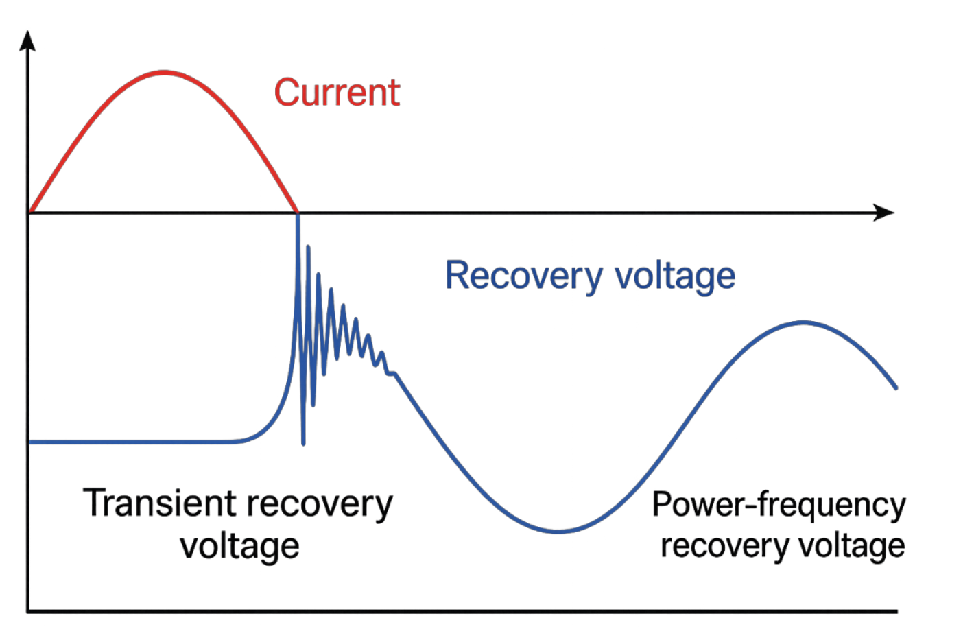
While the breaker remains closed, the potential difference across its contacts is practically negligible due to exceptionally low contact resistance. However, the moment the arc undergoes extinction at current zero, the voltage across the open gap experiences a sharp, incredibly rapid rise. This highly dynamic, immediate spike is termed the Transient Recovery Voltage (TRV). Once these high-frequency transient oscillations decay, the voltage stabilizes and mirrors the normal steady-state system waveform, known as the Power-Frequency Recovery Voltage.
The Phenomenon of Restrike
If the transient recovery voltage rises faster than the contact gap can insulate itself, the voltage stress will exceed the instantaneous dielectric strength of the insulation medium. This causes the arc to reignite violently across the gap, an occurrence known as a restrike. A restrike is not a separate category of voltage; rather, it is a dielectric insulation breakdown resulting from the transient voltage stress outstripping the breaker’s recovery capabilities.
Arc Interruption Theories
To mathematically evaluate and understand how an electric arc behaves during the clearing process, engineers rely on two fundamental arc models. Because the internal physics and thermal characteristics of the plasma shift dramatically as the current changes, different mathematical rules are required to map distinct stages of the arcing window.
Cassie’s Law: High-Current Arc Behaviour
Applied immediately following contact separation when the fault current remains substantial. During this early arcing phase, the contact clearance is narrow, the channel resistance is remarkably low, and the arc itself is intensely hot, strongly ionized, and highly stable.
- Models a rugged arc column with an approximately constant voltage drop.
- The arc dynamically cross-sections its diameter to accommodate massive current surges, keeping it stable and highly resilient to interruption.
- Forms the bedrock of arc quenching theory: if power can be extracted and cooled from the plasma channel faster than the surrounding power circuit injects electrical energy, the arc collapses.
Slepian’s Law: Low-Current Arc Behaviour
Dominates as the sinusoidal current naturally approaches its zero-crossing point. At this juncture, the total energy supplied into the plasma channel falls sharply, allowing external thermal cooling mechanisms to take precedence over power generation.
- Models the thermal cooling timeline of a weakening, highly unstable arc.
- Assumes a fixed rate of energy dissipation away from the arc core.
- As current plunges, the channel resistance escalates exponentially, driving the arc to a complete thermal extinction at the exact moment of current zero. This steep resistance surge is crucial for a clean interruption.
Dielectric Build-Up and Interruption Success
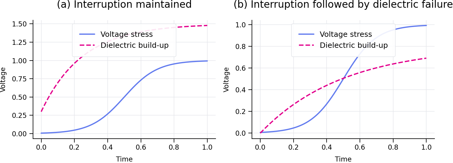
Once the current zero threshold is breached, the ultimate success of the interruption hinges entirely on a race between the dielectric recovery of the contact medium and the rising electrical stress from the power network.
-
(a) Interruption Maintained:
When the dielectric strength of the contact gap builds up at a rate strictly greater than the transient recovery voltage stress curve, the insulation layer holds, preventing any potential restrikes, and the fault is successfully cleared. -
(b) Interruption Followed by Dielectric Failure:
If the transient recovery voltage stress curve intersects or surpasses the dielectric build-up boundary line, the contact gap breaks down, resulting in an immediate restrike and full reignition of the arcing state.
Combined Arc Models in Practice
In practical modern engineering applications, neither Cassie’s nor Slepian’s equations are used in absolute isolation. Instead, power systems engineers utilize a sophisticated, integrated hybrid arc model. This combined approach introduces a smooth mathematical transition that starts with Cassie-type modeling at peak currents and shifts dynamically into Slepian-type modeling as the current closes in on zero.
Deploying this combined hybrid simulation methodology allows engineers to analyze the full life cycle of an arc realistically—from initial contact separation and active arcing to natural current zero extinction and ultimate transient voltage recovery. This enables precise assessments of breaker performance and potential restrike vulnerabilities under extreme network conditions.