

Per-unit (pu) analysis is a standard normalisation method in power system engineering that simplifies calculations across networks operating at multiple voltage levels. It works by expressing electrical quantities, such as voltage (V), current (I), apparent power (S), and impedance (Z), as ratios of selected base values.
This approach allows engineers to compare equipment ratings, combine impedances, and perform system studies without repeatedly converting between different voltage levels. In essence, per-unit analysis transforms a complex, multi-voltage network into a unified and more manageable model, making calculations straightforward and consistent. For example, it converts the following detailed network into a simplified equivalent representation:
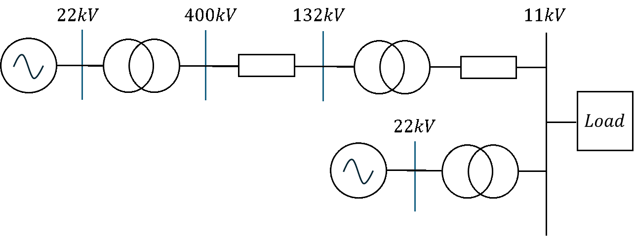
Figure 1: Detailed Multi-Voltage Grid Network.
Into this:
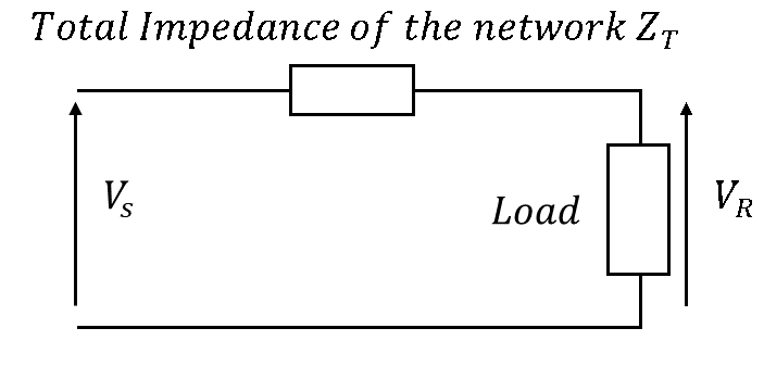
Figure 2: Normalized System Equivalent Circuit.
In a way its like Thevenins – it turns a circuit into a more simple form.
Why Use Per Unit Analysis?
Per-unit analysis reduces complex, multi-voltage systems to a unified representation. Transformers, lines, and loads can be modeled at their operating voltage with impedances converted to the same per-unit base, enabling straight forward addition and reduction of series or parallel paths.
The technique makes symmetrical fault calculations, voltage regulation studies, and busbar voltage evaluations tractable, especially when transformer ratios cause base voltages to change from one section to another. Moreover, manufacturer data for transformers and generators is often given in per unit (e.g., leakage reactance), which aligns naturally with system studies.
General Formula
The general formula used to solve a per-unit analysis problem is given by:
Per unit value = actual value of a quantity / base value of a quantity
Key Formulas
There are two primary formulas used when performing per-unit network calculations:
- Transformers and Generators These components typically have a per-unit impedance value provided by the manufacturer, based on their design characteristics. When converting this impedance to a different base for system calculations, the following formula is applied:
Zpu, new = Zpu given × (Sbase / Srated)
- Overhead Lines and Underground Cables For these assets, impedance is usually specified in ohms. To express this impedance in per-unit terms on the chosen base, use:
Zpu = (ZΩ × Sbase) / (Vbase)2
Here, Vbase represents the operating voltage of the asset.
Per-Unit Analysis – Solution Steps
Solving a per-unit network problem typically involves the following steps:
We will now apply these steps to determine the sending-end voltage for the transformer in the following network:

Figure 3: Single-Line Network Blueprint.
The system parameters are:
- Transformer 1: 200 MVA, 22kV/400kV, X = 0.1 pu
- OHL 1: X = j4.0 Ω inside the 400kV corridor.
- Transformer 2: 100 MVA, 400kV/132kV, X = 0.08 pu
- Load: 50 MW at 0.8 Power Factor Lagging across the 132kV endpoint.
Step 1 – Select a Common Base Power (SB)
Begin by choosing a single base power for the entire circuit. For this example, we will use 100 MVA as the base, as this is the typical value used within industry. However, any convenient value can be selected, provided it remains consistent throughout the analysis.
Step 2 – Convert Each Asset to the Common Base Impedance
- Transformer 1 (22/400 kV): Rated at 200 MVA with an impedance of 0.1 pu on its own base. To convert this to the 100 MVA base:
Zpu, new = Zpu, old × (Sbase / Srated) = 0.1 × (100 / 200) = 0.05 pu - Transformer 2: Already rated at 100 MVA, so its impedance remains unchanged at 0.08 pu.
- Overhead Line (OHL1): For the overhead line, the impedance is given in ohms. Convert it to per-unit using:
ZOHL1 = (ZΩ × Sbase) / (Vbase)2 = (j4.0 × 100 × 106) / (400 × 103)2 = j0.0025 pu
Step 3 – Reduce the circuit to allow a simple resolution
The common per unit values for each asset, can be used to simplify the network below:
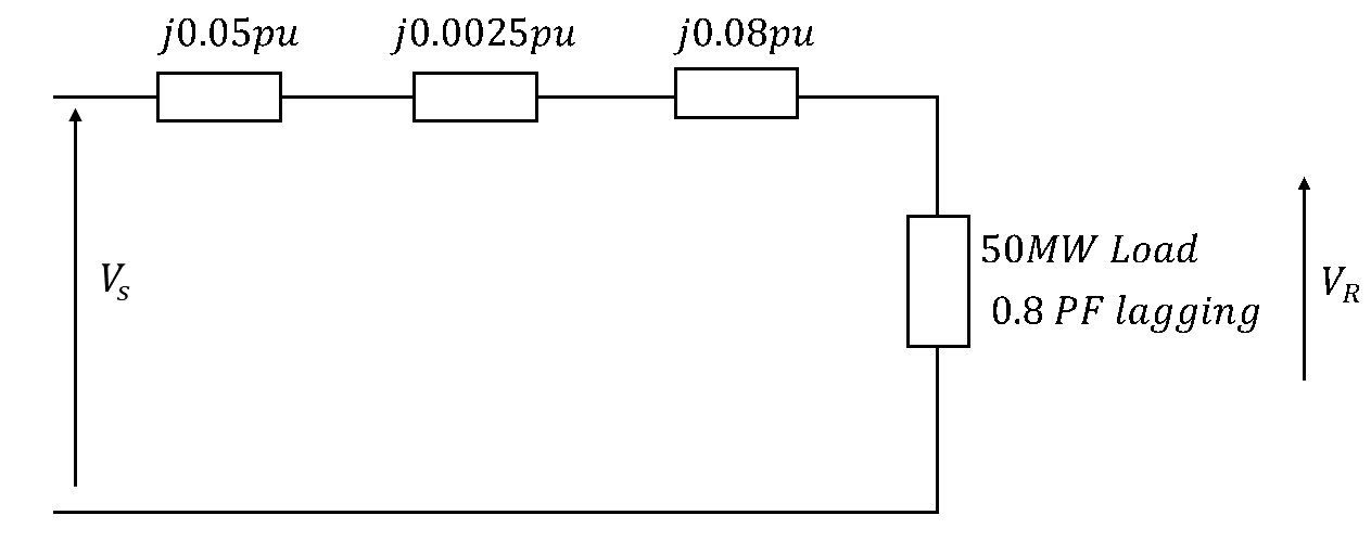
Figure 4: Series Reactance Network Parameter Mapping.
Total Impedances can be calculated as follows:
ZT = 0.05 + 0.0025 + 0.08 = j0.1325 pu
Step 4 – Performing required operation – calculating VS
The specified load values introduce a challenge. The problem defines the load in terms of real power P (in watts) rather than apparent power S (in volt-amperes), which is typically required for system calculations. Furthermore, the line current I is not provided, preventing calculation of the voltage, VS.
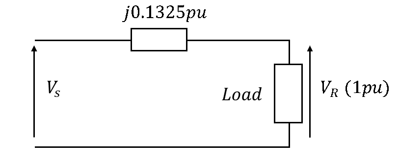
Figure 5: Equivalent Closed Single-Loop Solution Circuit.
Calculating apparent power of the load SL:
SL = PL / cos(φ) = V × I
Therefore, SL = 50 / 0.80 = 62.5 MVA
Calculating the current I:
We do not have a value for I, we can use the power values of the load as a ratio with the base power (SB) to give a per unit value of current, as the current is determined by load.
IL, pu = SL / SB = 62.5 / 100 = 0.625 pu
Calculating the current I angle:
IL, pu gives a value of 0.625, this is the magnitude of the current. The angle is given by cos-1(0.8) = 36.9° Lagging = -36.9°.
In rectangular form this gives IL, pu as 0.4998 – j0.3753 pu.
Because the system is operating normally at its rated endpoint voltage of 132kV, our receiving-end reference voltage VR is exactly 1.0 with an angle of 0 pu. Calculating the sending end voltage VS:
VS = VR + (IL pu × ZT)
VS = 1 + j0 + (0.4998 – j0.3753) × (0 + j0.1325) = 1.0497 + j0.066 pu
VS = √(1.04972 + 0.0662) = 1.0518 pu
Converting from the per-unit to the actual value:
VS = 1.0518 × 132 kV = 138.8 kV
Calculation of a Short Circuit Fault Current in a 3-Phase Balanced Fault.
Step 4 – Performing required operation – balanced fault calculations MVAS/C & IS/C
A 3-phase balanced fault occurs just before our 50 MW load.

Figure 6: Balanced 3-Phase Short Circuit Bus Fault Layout.
To calculate the balanced fault apparent power (MVAS/C) we need to know the magnitude of the total impedance to the point of fault.
Calculating the magnitude of total impedance |ZT|:
ZT = √(02 + 0.13252) = 0.1325 pu
(Note: There is no resistance, so the magnitude is just the imaginary part only)
Calculating the balanced fault power:
MVAS/C = SB / |ZT| = 100 / 0.1325 = 754.7 MVA
To determine the balanced short-circuit fault current (IS/C), it is necessary to know the fault apparent power (Sfault) and the system voltage at the fault location. These parameters allow calculation of the current magnitude under balanced fault conditions.
Calculating the short circuit fault current IS/C:
IS/C = MVAS/C / (√3 × V) = 754.7 × 10⁶ / (√3 × 132 × 103) = 3301 A = 3.3 kA