
Synchronous Motors: Theory & Performance
What is a Synchronous Motor?
A synchronous motor is an alternating current (AC) motor whose rotor rotates at exactly the same speed as the rotating magnetic field produced by the stator windings. Utilizing direct current (DC) excitation on its rotor, this class of machine operates with zero slip under steady-state conditions, making it an ideal choice for constant-speed, high-efficiency industrial applications.
Induction Motors vs. Synchronous Motors
Induction and synchronous machines differ fundamentally in their underlying operational physics and how their rotational speed responds to mechanical load variances.
Induction Motors
Operate strictly via electromagnetic induction. The stator’s rotating magnetic field induces electrical currents inside the rotor structure, creating the torque needed for rotation.
- The rotor must always run slightly slower than synchronous speed; this functional difference is known as slip, which naturally widens as the mechanical load increases.
- Highly robust, structurally simple, and inherently self-starting.
- Commonly deployed for pumps, fans, and conveyors, though they typically operate at a lagging power factor.
Synchronous Motors
Incorporate independent DC excitation or powerful permanent magnets on the rotor assembly. This allows the rotor’s magnetic poles to physically lock in step with the stator’s rotating field.
- Runs at an exact synchronous speed with zero slip, completely independent of the mechanical load magnitude.
- They are not self-starting; they require external starting mechanisms, such as a damper cage or a pony motor, to accelerate the rotor close to synchronous speed before interlocking occurs.
- More complex and expensive, but deliver exceptional efficiency and flexible control over lagging, unity, or leading power factors.
Starting Dynamics & Operational Factors
Because a stator produces its high-speed rotating magnetic field immediately upon energization, a stationary rotor experiences alternating forward and backward torques too rapidly to overcome its own inertia. Consequently, the rotor must first be mechanically or inductively accelerated to near-synchronous speed before the DC field excitation is applied to pull the machine into perfect synchronism.
Once synchronized and operating smoothly, the ongoing performance of a synchronous motor is governed primarily by two adjustable system parameters:
- Changes in Shaft Load: Affects the physical torque angle (load angle) between the stator and rotor magnetic fields without changing the speed.
- Changes in Field Excitation: Adjusting the DC current allows the operator to control the reactive power behavior. Supplying a high excitation current causes the motor to run at a leading power factor, acting as a valuable asset for improving the overall power factor of an industrial facility.
Worked Performance Problems
Example Problem 1
Scenario: A 400 V, 8-pole, three-phase, 50 Hz star-connected synchronous motor has a stator resistance of 0.40 Ω and a synchronous reactance of 7 Ω. The motor initially draws a line current of 15 A at unity power factor.
Part A: Determine the internally generated EMF (E) and mechanical load angle (δ).

IR Drop = 15 A × 0.4 Ω = 6 V
IX Drop = 15 A × 7 Ω = 105 V
VZS = √(105² + 6²) = 105.2 V
Internal Impedance Angle (θ) = tan¹(105 / 6) = 86.7°
The Above could be drawn as follows, which helps with the representation and understanding.

Applying Cosine Rule to find E:
E² = 230.9² + 105.2² – 2 × 230.9 × 105.2 × cos(86.7°)
E = 253.2 V
Applying Sine Rule to find Electrical Load Angle (δ):
253.2 / sin(86.7°) = 105.2 / sin(δ) → δ = 24.5° (Electrical)
Mechanical Load Angle = δ / Pole Pairs = 24.5° / 4 = 4.08°
Part B: The excitation remains unchanged, but load torque increases until the current reaches 50 A. Find the new load angle and power factor.
Analysis Note: Since E and V remain constant while current increases, the internal voltage drop vector VZS must pivot upwards to maintain a valid closed triangle, causing the stator current to lag behind the phase voltage.

New IX Drop = 50 A × 7 Ω = 350 V
New VZS = √(350² + 20²) = 350.6 V
Impedance Angle (θ) remains 86.7°
Using Cosine Rule with known E (253.2 V) to find angle γ:
253.2² = 350.6² + 230.9² – 2 × 350.6 × 230.9 × cos(γ)
γ = 46.2°
Calculate New Power Factor:
Phase Angle (φ) = θ – γ = 86.7° – 46.2° = 40.5°
Power Factor = cos(40.5°) = 0.760 lagging
Calculate New Load Angle via Sine Rule:
253.2 / sin(46.2°) = 350.6 / sin(δ) → δ = 88.0° (Electrical)
Mechanical Load Angle = 88.0° / 4 = 22.0°
Example Problem 2
Scenario: A 400 V, 8-pole, three-phase, 50 Hz star-connected synchronous motor operates with a synchronous reactance of 7 Ω and negligible winding resistance. The motor draws a line current of 15 A at a leading power factor of 0.78.
Solution Steps:

Because resistance is negligible, Winding Impedance Angle (θ) = 90°
VZS = I × X = 15 A × 7 Ω = 105 V
Phase Angle (φ) = cos¹(0.78) = 38.74°
Total Vector Angle (γ) = 90° + φ = 90° + 38.74° = 128.74°
Applying Cosine Rule to evaluate E:
E² = 230.9² + 105² – 2 × 230.9 × 105 × cos(128.74°)
E = 307.71 V
Applying Sine Rule for Load Angle calculation:
307.71 / sin(128.74°) = 105 / sin(δ) → δ = 15.4° (Electrical)
Mechanical Load Angle = 15.4° / 4 = 3.85°
Example Problem 3
Scenario: An industrial facility operates with an existing baseline load of 500 kVA at a lagging power factor of 0.7. A new synchronous motor drawing 150 kW of active power is integrated into the facility to improve the plant-wide power factor to 0.9 lagging.
Solution Steps:
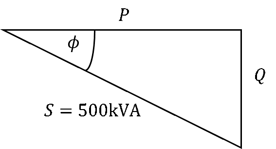
Original Phase Angle (φold) = cos¹(0.7) = 45.6°
Original Active Power (Pold) = 500 × cos(45.6°) = 349.8 kW
Original Reactive Power (Qold) = 500 × sin(45.6°) = 357.2 kVAr

Target Phase Angle (φnew) = cos¹(0.9) = 25.8°
Target Facility Reactive Power (Qnew) = 349.8 × tan(25.8°) = 168.7 kVAr
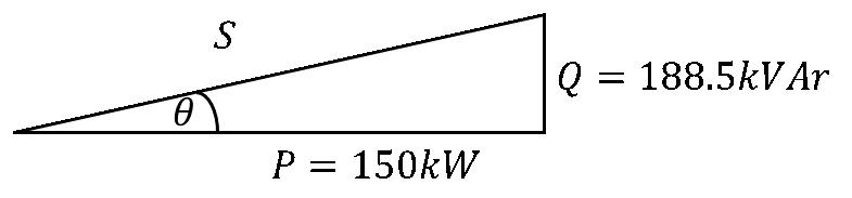
Required Motor kVAr = Qold – Qnew = 357.2 kVAr – 168.7 kVAr = 188.5 kVAr
Motor Internal Power Angle (θ) = tan¹(188.5 / 150) = 51.5°
Motor Apparent Power (S) = √(188.5² + 150²) = 240.9 kVA
Motor Operating Power Factor = cos(51.5°) = 0.622 leading