

Electrical Insulators
What Are Insulators?
In an electrical power grid, insulators are components that prevent unwanted flow of electricity while allowing conductors to be mechanically supported and safely positioned.Their role is both electrical and structural, and they are essential for safe, reliable grid operation.
Electrically, insulators separate live conductors from grounded structures such as towers, poles, and substations.High-voltage equipment operates at potentials that would cause current to flow to earth if a conductive path existed.Insulators provide very high electrical resistance, ensuring electricity remains confined to the conductors and equipment it is intended to flow through, rather than leaking into supporting structures or the surrounding environment.
Mechanically, insulators support the physical weight and tension of overhead lines and substation busbars.Transmission conductors are heavy and subjected to mechanical forces such as wind, ice loading, and thermal expansion.Insulators transfer these forces safely to towers or gantries while maintaining electrical separation.Different designs, such as suspension insulators and strain insulators, are selected based on the mechanical loads present.
Environmentally, insulators are designed to withstand weather, pollution, and contamination.Outdoor grid equipment is exposed to rain, fog, salt, dust, and industrial pollution.Insulators maintain adequate surface leakage distance to prevent flashover, where current travels over the surface rather than through the air.In more aggressive environments, longer or specially profiled insulators are used.
From a safety perspective, insulators protect people, animals, and equipment.By maintaining electrical isolation, they reduce the risk of electric shock, fires, and damage to grid assets.A failed or contaminated insulator can lead to flashovers, faults, or outages, which is why insulator condition is a critical part of grid maintenance.
How Are They Constructed?
Electrical grid insulators are constructed to combine high electrical resistance, mechanical strength, and environmental durability.While designs vary by voltage level and application, their construction follows the same core principles.At a high level, an insulator consists of an insulating body, metal end fittings, and a bonding interface that permanently joins the two.
The insulating body is the main part and is made from one of three materials. Traditional insulators are made from porcelain, which is produced by firing refined clay and alumina at high temperatures to form a dense ceramic with excellent dielectric strength.Porcelain insulators are usually coated with a glass glaze to seal the surface and reduce moisture absorption. Another common material is toughened glass, used mainly for disc insulators on transmission lines.Molten glass is moulded and rapidly cooled so the surface is in compression, giving high mechanical strength and predictable failure behaviour. Modern designs increasingly use composite (polymer) materials, typically silicone rubber bonded to a fiberglass-reinforced epoxy core.These materials provide excellent pollution performance and high strength with much lower weight.
The core or load-bearing structure depends on the insulator type. In porcelain and glass insulators, the ceramic or glass body itself carries the mechanical load. In composite insulators, the load is carried by a fiberglass rod, which provides high tensile strength, while the silicone rubber housing provides electrical insulation and environmental protection.
Metal end fittings are attached to the insulating body to allow installation on towers, crossarms, or equipment.These fittings are typically made from forged or cast steel or malleable iron and are galvanised to prevent corrosion.Common arrangements include pin fittings, cap-and-pin designs for suspension strings, and end clevises for long-rod insulators.
The bonding process between the insulating body and the metal fittings is critical. For porcelain and glass insulators, the fittings are attached using cement (usually Portland cement with additives), which mechanically locks the metal to the insulating body once cured. For composite insulators, the metal fittings are typically crimped onto the fiberglass core and then sealed, rather than cemented, creating a strong mechanical joint that is resistant to vibration and ageing.
To improve electrical performance, the outer surface of the insulator is shaped with sheds or skirts.These increase the creepage distance, which helps prevent surface leakage currents and flashover, particularly in polluted or wet environments.In composite insulators, the silicone rubber surface also has hydrophobic properties, causing water to bead rather than form a continuous conductive film.
Finally, insulators undergo factory testing before installation. This typically includes mechanical tensile tests, power-frequency withstand tests, impulse voltage tests, and environmental ageing tests.These confirm that the construction meets both electrical and mechanical design requirements for long-term grid operation.
What Makes a Good Insulator?
A good insulator in an electrical grid context is one that reliably prevents unwanted current flow, withstands mechanical stresses, and maintains performance over decades of service under harsh environmental conditions.Its quality is judged by a combination of electrical, mechanical, and environmental properties rather than a single factor.
A good insulator has high electrical resistance and dielectric strength, meaning it can withstand the operating voltage and expected overvoltages (such as lightning or switching surges) without allowing current to pass through or along its surface.This ensures electricity stays confined to conductors and does not leak to earth or supporting structures, which is critical for safety and system reliability.It also possesses sufficient creepage distance, which is the path length along the surface of the insulator between energised and grounded parts.A longer creepage distance reduces the risk of surface leakage currents and flashover, particularly during wet, polluted, or salty conditions.Good insulators are therefore shaped with sheds or skirts to manage contamination and moisture effectively.
A good insulator must have strong mechanical performance. In overhead lines, insulators support the weight of conductors and must withstand tensile loads from conductor tension, wind pressure, ice loading, and mechanical vibration.In substations, they carry equipment loads and resist cantilever and compression forces.Mechanical strength must be maintained throughout the insulator’s service life.
Environmental durability is another key requirement. A good insulator resists degradation caused by ultraviolet radiation, temperature cycling, pollution, chemical exposure, and moisture ingress.For composite insulators, this includes maintaining surface hydrophobicity, while for ceramic and glass insulators it means resisting cracking, glaze damage, and gradual surface tracking.
From an operational standpoint, a good insulator exhibits predictable failure behaviour.Toughened glass insulators, for example, shatter visibly when they fail, allowing easy detection during inspections, while composite insulators are designed to degrade gradually rather than catastrophically.This predictability improves maintenance planning and system safety.
A good insulator also requires low maintenance and long service life.Modern grid assets are expected to remain in service for several decades, often in remote locations.Insulators that retain their electrical and mechanical properties with minimal cleaning or replacement are preferred, as they reduce lifecycle costs and outage risk.
Modelling the Distribution Across a String of Insulators
To assist with understanding, if the insulator string is considered as part of a direct-current circuit in which all suspension insulator units are identical, the voltage would be expected to divide equally across each insulator disc.In this case, a leakage current would flow through each disc, and the voltage across an individual unit would simply be the product of this leakage current and the resistance of that unit.
However, when the applied voltage is alternating, the voltage distribution along the insulator string is no longer uniform. This unequal distribution arises due to differences in charging currents within the string. Each insulator disc incorporates metal fittings, and these fittings form a capacitance relative to the fittings of adjacent units, referred to as the mutual capacitance, denoted as C. In addition, a capacitance exists between the metal fittings and the tower or earth, known as the capacitance to ground, Cg.
The presence of this mutual and ground capacitance causes part of the charging current to bypass individual insulator discs rather than flowing exclusively through each unit. As a consequence, the insulator disc closest to the crossarm experiences the lowest voltage stress, while the disc nearest the line conductor is subjected to the highest voltage. The method described in these notes neglects the capacitance between the conductor and the metal link and is therefore not applicable to composite insulators.
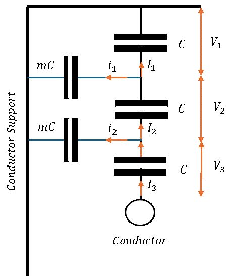
Figure 1: Equivalent Capacitance Model of a 3-Unit Insulator String.
Where m = Capacitance to Ground / Mutual Capacitance
Using Kirchhoff’s Current Law:
I2 = i1 + I1
To express this relationship in terms of voltage, we utilize capacitive reactance relationships:
XC = 1 / (2πfC)
This yields individual current expressions:
- I2 = V2 / XC = V2 / (1 / (2πfC)) = V2 · 2πfC
- I1 = V1 / XC = V1 / (1 / (2πfC)) = V1 · 2πfC
- i1 = V1 / XmC = V1 / (1 / (2πfmC)) = V1 · 2πfmC
Substituting these values into the network node equation:
V2 · 2πfC = V1 · 2πfmC + V1 · 2πfC
V2 = V1m + V1 = V1(1 + m)
Applying this same methodology sequentially down the string, noting that the capacitive grounding effect accumulates down the structure:
I3 = i2 + I2 + i1
V3 · 2πfC = V2 · 2πfmC + V2 · 2πfC + V1 · 2πfmC
V3 = V2m + V2 + V1m
Substituting the value calculated for V2 into the equation:
V3 = m(V1m + V1) + V1m + V1 + V1m
V3 = V1m2 + V1m + V1m + V1 + V1m
V3 = V1(m2 + 3m + 1)
Example Application Analysis
In a string of 3 units the capacitance between each link pin to earth is 18% of the capacitance of one unit (m = 0.18).Calculate the voltage across each unit and the string efficiency when the voltage across the string is 33kV.
Step 1: Express Disc Voltages in Terms of V1
V2 = V1m + V1 = V1(1 + 0.18) = 1.18V1
V3 = V1(m2 + 3m + 1) = V1(0.182 + 3(0.18) + 1) = 1.57V1
Step 2: Balance Potentials with Total String Voltage
The total potential difference across the string must add up to 33kV:
33kV = V1 + V2 + V3 = V1 + 1.18V1 + 1.57V1 = 3.75V1
V1 = 33k / 3.75 = 8.80kV
Step 3: Solve for Individual Component Voltages
- V1 = 8.800kV
- V2 = 1.18 · 8.8kV = 10.384kV
- V3 = 1.57 · 8.8kV = 13.816kV
Observation: The insulator closest to the line conductor (V3) always experiences the greatest electrical potential difference across it.
Why Is This the Case?
The underlying cause of the non-uniform voltage distribution along an insulator string is the cumulative capacitance that exists between each insulator unit and the supporting structure, such as the tower or crossarm. Each insulator disc does not operate in isolation; instead, the capacitance between the metal fittings of the insulators and earth increases progressively for units closer to the support. As a result, the capacitive coupling to ground effectively accumulates along the string, influencing how the applied voltage is shared between individual insulators.
In an ideal situation, the potential difference would be evenly distributed across all insulator units so that each disc experiences the same electrical stress. This would maximise utilisation of the insulation material and improve overall reliability. In practice, however, this is not achievable due to the presence of mutual capacitance between adjacent units and capacitance to ground, which causes part of the charging current to bypass individual insulators. While a perfectly uniform distribution is impossible, careful design can produce insulator strings that are more efficient than others in terms of how evenly the voltage is shared.
Quantifying Performance: String Efficiency
The effectiveness of an insulator string in distributing voltage is quantified using the concept of string efficiency, which compares the average voltage per insulator to the maximum voltage appearing across any single unit. A higher string efficiency indicates a more uniform voltage distribution and reduced electrical stress on the most highly loaded insulator, typically the one nearest the conductor.
η = Conductor voltage / (N × V)
Where N = number of insulators in the string, V = voltage of insulator closest to conductor
It is essential that individual insulators are mechanically and electrically robust enough to withstand the maximum potential difference they may experience in service. If an insulator is subjected to a voltage stress beyond its design limit, internal breakdown or surface flashover can occur, potentially leading to cracking, shattering, or permanent loss of insulating capability. Such failures compromise system safety and can result in outages or damage to adjacent equipment.
For these reasons, voltage distribution along an insulator string is inherently non-uniform, particularly under alternating current conditions and at high voltage levels. To mitigate this effect and protect the most heavily stressed units, grading techniques such as grading rings are commonly employed. These devices modify the electric field distribution around the string, reducing the voltage concentration at the conductor end and improving the overall string efficiency, thereby enhancing both reliability and service life in high-voltage applications.