What is a synchronous motor
A synchronous motor is an AC motor whose rotor rotates at the same speed as the stator’s rotating magnetic field. It uses DC excitation, has no slip, and is ideal for constant‑speed, high‑efficiency industrial applications.
Induction Motors vs. Synchronous Motors
Induction motors and synchronous motors differ mainly in how they operate and how their speed responds to load. An induction motor works through electromagnetic induction: the stator produces a rotating magnetic field that induces current in the rotor, causing it to turn. Because the rotor relies on induced current, it always runs slightly slower than synchronous speed—a difference known as slip, which increases as the load rises. These motors are robust, simple, self‑starting, and commonly used in applications such as pumps, fans, and conveyors, though they typically run at a lagging power factor.
Synchronous motors, on the other hand, use either DC excitation or permanent magnets on the rotor, enabling the rotor to lock into the stator’s rotating magnetic field and run at exact synchronous speed with zero slip, regardless of load. They do not self‑start and require additional methods, such as a damper cage, or pony motor, to bring the rotor close to synchronous speed before it can lock in. While more complex and expensive, synchronous motors offer high efficiency and the ability to operate at leading, unity, or lagging power factor. With high excitation current, they run at a leading power factor, making them valuable for improving overall industrial power factor.
Because the stator immediately produces a rotating magnetic field at energisation, a stationary rotor cannot synchronise with it. The rotor must first be accelerated to near‑synchronous speed before DC excitation is applied to pull it into synchronism. Once running, the performance of a synchronous motor is mainly influenced by two factors:
- Changes in load
- Changes in excitation
Example 1
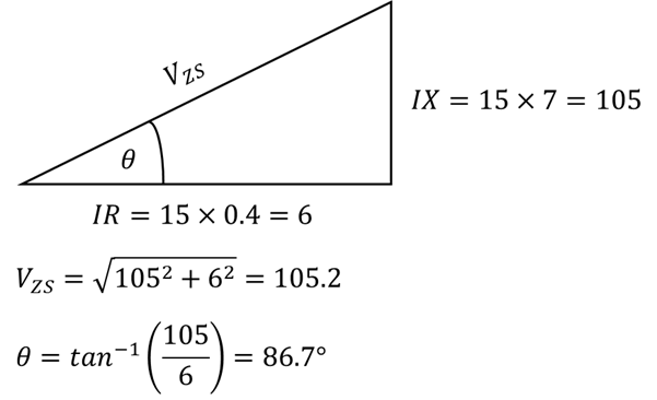
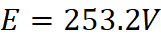
A 400V, 8‑pole, three‑phase, 50 Hz star‑connected synchronous motor has a stator resistance of 0.40 Ω and a synchronous reactance of 7 Ω. When the motor draws 15 A at unity power factor, determine the internally generated EMF and the mechanical load angle.
If the excitation remains unchanged but the load torque is increased so that the current rises to 50 A, determine:
(i) The new load angle
(ii) The resulting power factor

Note: In a purely inductive load, the angle would be 90 degrees.
The Above could be drawn as follows, which helps with the representation and understanding.


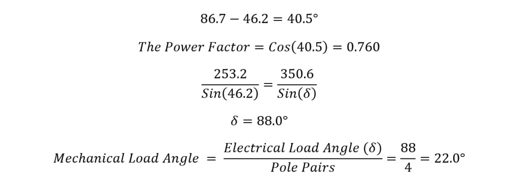
The electrical load angle is the angle of the whole system not per pole, so we have to work it out per pole as shown below:
For this section of the question:
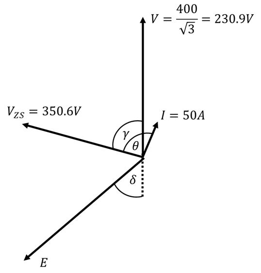
If the excitation remains unchanged but the load torque is increased so that the current rises to 50 A.
If the excitation remains unchanged and the current rises, VZS due to IX and IR increasing. But remember that V, Vzs and E need to make a triangle, so if E and V is constant. Vzs must have to pivot up to meet E. But the angle theta must remain the same, which would then make I (the load) start to lag. Therefore, the following must be true:

This time we know E!!!
But we only know Theta! As this is the angle from Vzs and I not V.
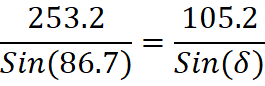
We have 3 sides and are looking for an angle. So, we can use cosine rule.

We know and now
. The phase angle is the angle between V and I, therefore the phase angle can be calculated as follows:
Example 2
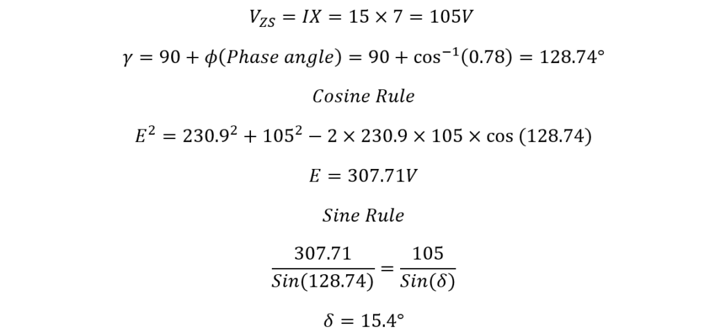
A 400V, 8‑pole, three‑phase, 50 Hz star‑connected synchronous motor has a stator a synchronous reactance of 7 Ω, and the resistance is negligible. When the motor draws 15 A at Leading power factor of 0.78, determine the internally generated EMF and the mechanical load angle.
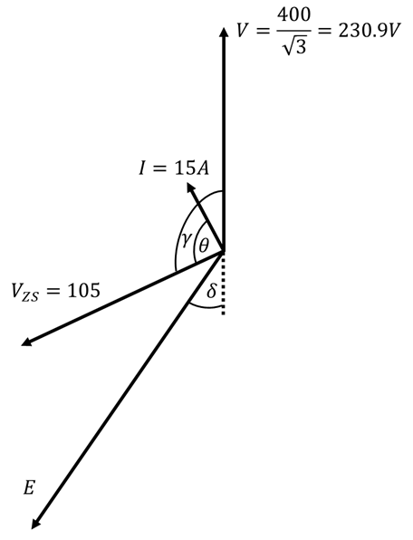
There is no resistance, therefore we know reactance is 90 degrees out of phase. Therefore:
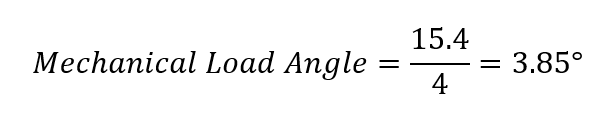
This is the electrical load angle; to work out the mechanical load angle, we divide by the number of poles pairs.
Example 3
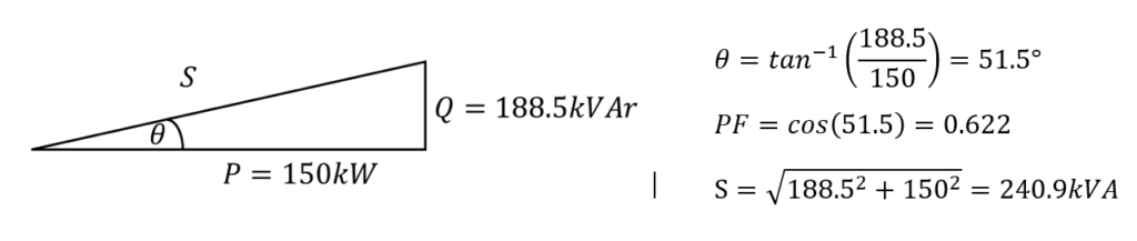
A factory has a load of 500 kVA operating at a lagging power factor of 0.7. A synchronous motor is to be installed to improve the overall power factor to 0.9. When operating, the motor draws 150kW. Determine the required kVA rating of the motor and the power factor at which the motor must operate.
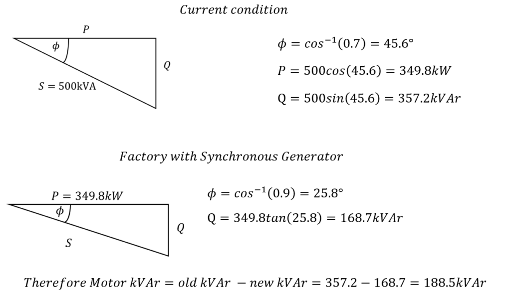
Therefore we know the motors power triangle. We have been given P in the question and now we have worked out the required Q, to increase power factor to 0.9. We just need to workout the motors apparent power and power factor.