
Transformer Equivalent Circuit
Introduction
A transformer is an essential device used in electrical circuits to modify voltage and current levels. It serves a vital function within the energy network by facilitating the efficient transmission of electricity. Additionally, transformers help to regulate and maintain voltage levels within a range that is suitable for consumers, ensuring that the electricity supplied is both safe and effective for use.
A transformer is composed of two wire windings that are positioned around a magnetic iron core, and it operates based on the principles outlined in Faraday’s Law of electromagnetic induction. The winding that is connected to the power source is called the primary winding, while the winding that connects to the load is referred to as the secondary winding. The primary winding receives electrical energy from the power source, which generates a magnetic field around the iron core. This magnetic field is crucial as it facilitates the transfer of energy between the two windings. As the magnetic field fluctuates, it induces a voltage in the secondary winding, effectively converting the electrical energy from the primary winding into magnetic energy, this magnetic energy is then transformed back into electrical energy in the secondary winding, allowing it to supply power to the connected load. Transformers are fundamental components in electrical systems, enabling the efficient transmission and distribution of electricity across various distances. By adjusting voltage levels, they help to ensure that electrical energy can be delivered safely and effectively to homes and businesses, while also minimizing energy losses during transmission[1].
Transformers are not completely efficient, with typical efficiency ratings hovering around 98%. This means that there are inherent losses within the components of each transformer that prevent it from achieving 100% efficiency. These losses can arise from various factors, including resistance in the wire windings, core losses due to hysteresis and eddy currents, and other thermal losses. Understanding the efficiency of transformers is crucial for accurately drawing their equivalent circuits. The equivalent circuit represents the transformer’s behaviour in a simplified manner, allowing engineers to analyse its performance under different operating conditions. By accounting for the inefficiencies, one can better predict how the transformer will respond to varying loads and voltages, ultimately leading to more effective design and operation within electrical systems. This knowledge is essential for optimizing transformer performance and ensuring reliable energy distribution[2].
One of the challenges of incorporating a transformer into a network is that performing calculations can be quite complex. One effective way to address this issue is by using an equivalent circuit. This equivalent circuit assumes that the transformer is ‘ideal,’ meaning it has no inefficiencies, and any losses are represented as components added into the circuit[2], as shown in Figure One.
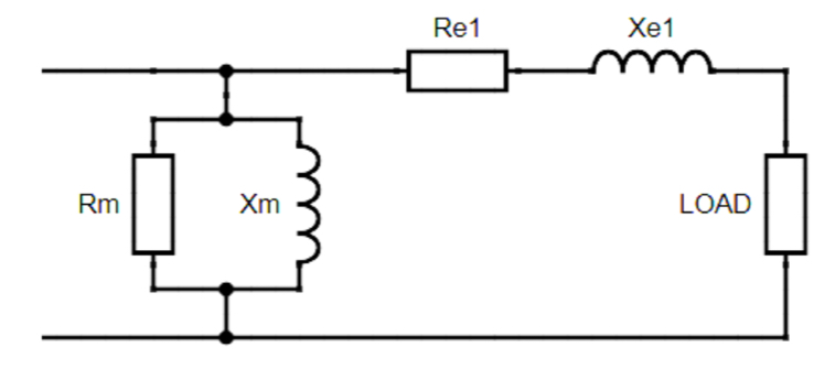
Figure One: Approximate Equivalent Circuit. Where Xe1 and Re1 represents the resistance and reactance in the windings and the Rm and Xm of the core.
To evaluate the inefficiencies in a transformer, two primary tests can be performed: the open circuit (O/C) test and the short circuit (SC) test. The open circuit test is designed to determine the actual turns ratio of the transformer as well as the magnetising components, specifically the resistance (Rm) and reactance (Xm). This test provides valuable data that aids in calculating the magnetic inefficiencies associated with the conversion of electrical energy into magnetic energy within the core. By understanding these parameters, engineers can better assess how effectively the transformer operates under no-load conditions. On the other hand, the short circuit test focuses on calculating the winding resistance and the leakage reactance of both the primary and secondary windings when they are combined on the primary side. This test is conducted by applying a reduced voltage to the transformer while shorting the secondary winding, allowing for the measurement of losses that occur due to the resistance of the windings and the leakage reactance. The results from the SC test are essential for understanding the transformer’s performance under load conditions and for identifying any potential inefficiencies that may affect its overall operation. Together, these tests provide a comprehensive assessment of a transformer’s efficiency and performance characteristics, enabling engineers to make informed decisions regarding design and operational improvements[3].
Example tests will be shown below on how an equivalent circuit can be made.
Open Circuit (O/C) Test
An example of an O/C test produced the results shown in Figure Three. The graph shows a linear correlation between the primary and secondary voltages. The transformer is rated at as one-to-one transformer(230/230V). However, the transformer is not ‘ideal’. It has been determined that the secondary voltage is stepped up to approximately 1.09 times the primary voltage as can be seen by the gradient of the graph.
During an open circuit (O/C) test, the secondary circuit is left unconnected, leading to minimal copper losses. The only current that flows is the magnetising current, along with core losses, which include hysteresis and eddy current losses.
Continuing with the above example, if the primary voltage was set to 230V:

The core inefficiencies, represented as Rm and Xm in Figure Two, can be calculated as follows:

Short Circuit Test
For example, if there the following Short Circuit test results are as follows:

The combined windings inefficiencies, represented as Re1 and Xe1 in Figure Two, can be calculated as follows:

The equivalent circuit therefore is as follows:

Figure Two: Equivalent circuit with calculated values.
Losses
Every transformer experiences losses, including heat loss, which occurs due to the inherent resistance of copper that generates heat, as described by the formula P = I²R. Additionally, all windings incur losses in the form of reactance. When AC flows through a winding, it creates a magnetic field. Changes in the current alter this magnetic field, inducing a voltage that opposes the change in current, a phenomenon known as Lenz’s law[4].
Most of the flux lines from the magnetic field created from the windings will travel the path of least reluctance, which is also known as resistance for magnetic flux. Materials, like the core, have high permeability so the flux lines will flow. However, flux lines going in the same direction can repel each other so ultimately some of the flux lines are pushed into open space and do not end up cutting the secondary winding[1].
Eddy currents can also be formed as part of the loss. This is when an electric current is formed and spirals travels in a spiral direction, due to the change in magnetic flux. These eddy currents produce a loss in the form of heat within the core[5].
There is some additional Hysteresis loss which occurs in the core when the magnetic field changes direction and the cores ability to change or resist the change of magnetisation, this is known as the coercivity[6].
Transformer Full-Load Test
The load resistance for the transformer that would be required to draw rated current from the secondary is as follows:

Assuming that voltage on secondary is 230V:

Using the resistors in parallel gives a resistance of the following:

With the primary voltage set to 230V the off-load primary current is re-recorded. The resistance is set to 546Ω and the current is recorded in the following table:

If the transformer is ‘ideal’ the following equation applies:

An ideal transformer is characterised by having no losses, no leakage flux, and an infinitely permeable core[7]. Under these conditions, the secondary values would be expected to match the primary values. However, there are losses within the system. The off-load primary current represents the magnetising current and the inefficiencies within the core, as it is considered an O/C.
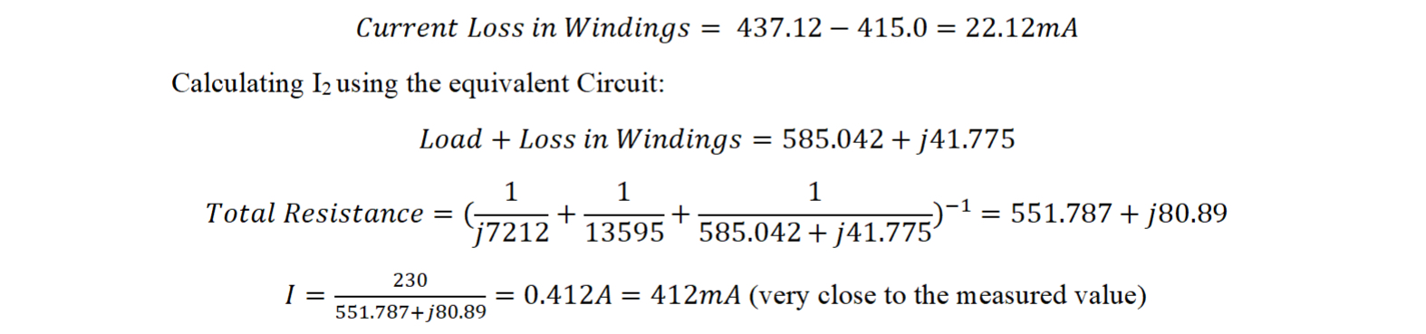
In an O/C, there is no load connected; The only current flowing is the energy used to magnetise the core, which is measured at 35.88 mA. If we consider this 35.88 mA as the total losses, we expect the following relationship to hold true:

When there is no load, a small current still flows on the primary side; this is the magnetising current used to energise the core. As mentioned earlier, the magnetising current alone does not account for the total difference. The reason for this discrepancy is that the open circuit current does not consider the losses in the windings. These losses can be calculated as the difference between the expected and actual currents.
Transformer On-Load Test (Voltage Regulation & Efficiency)
The Voltage regulation is the transformers ability to maintain a constant voltage output, even though variations in load. It is an important characteristic that indicates how well a transformer can perform under different loading conditions[8].
Transformers have internal impedance, which causes a voltage drop; this impedance consists of resistance and reactance, leading to current lagging behind voltage. A purely inductive load increases this lag, resulting in decreased voltage. In contrast, a purely capacitive load creates a leading power factor that counteracts impedance, improving voltage regulation[9].
When connected to a resistive load, a phase angle is not changed by the load, therefore enhancing voltage regulation and efficiency with minimal reactive power. The closer the operation is to a purely resistive load, the higher the voltage drop as there is no phase angle change resulting in a greater magnitude impedance. Hence, greater voltage regulation percentage. [9].
Lower impedance results in lower regulation which is desirable. However, this at the expense of the fault current, which increases due to the decrease in impedance[11].
Determination of Operating Point of Maximum Efficiency
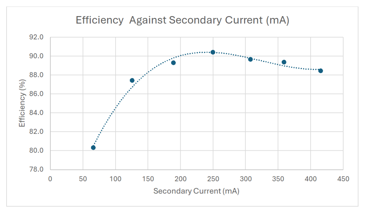
Figure Three: Efficiency Against Secondary Current
Figure Six shows the relationship between efficiency and secondary current. The graph indicates that maximum efficiency occurs at a current of 250.1mA with a load resistance of 950 Ω.
It is important to note that at maximum efficiency, the copper loss should equal the iron loss, according to the efficiency formula. However, the losses are not exactly the same in this case. This discrepancy may be due to the efficiency not being precisely at its maximum or potential errors in the measuring equipment[10].
References
[1] G. Shultz, Transformers and Motors, Chantilly. Elsevier Science, 1997. Available at: http://www.123library.org/book_details/?id=37557
[2] R. Singuor, P. Solanki, N. Pathak, D. Suresh Babu. “Simulation of Single Phase Transformer with Different Supplies”, International Journal of Scientific and Research Publications, Volume 2, Issue 4, Apr 2012
[3] S. Malor, “Open Circuit And Short Circuit Test Of Transformer,“ South Asian Journal of Marketing & Management Research, Volume 12, Issue 1, Jan 2022,
[4] W. Hurley, Transformers and Inductors for Power Electronics Theory, Design and Applications. Newark: John Wiley & Sons, 2013, [Online]Available at: https://public.ebookcentral.proquest.com/choice/PublicFullRecord.aspx?p=7103792
[5] F. Dubas, “Permanent-Magnet Eddy-Current Losses: A Global Revision of Calculation and Analysis,” Mathematical and Computational Applications, Volume 24, Jul 2019, DOI: 10.3390/mca24030067
[6] Feng, S. “Hysteresis loss free soft magnetic ferrites based on Larmor precession,” Chinese Physics B, 32(8), 2023, https://doi.org/10.1088/1674-1056/acbdec.
[7] A. Akhtar. “Ideal Transformer”, “Circuit Globe”. Accessed: 28 Mar 2025 [Online]. Available: What is an Ideal transformer? – its Phasor Diagram – Circuit Globe
[8] E. Hughes, Hughes electrical & electronic technology. Twelfth edition. Harlow: Pearson Education Limited, 2016
[9] M. Gangaraju, “An Evaluation Of Transformer Voltage Regulation.” Special Issue On Fundamentals Of Transformers, p.31. January 2022
[10] “Transformer Formulas and Equations”, Electrical Technology, Accessed: 21 Mar 2025. [Online]. Available: Transformer Formulas and Equations – Electrical Technology
[11] J. Harlow, “Electric Power Transformer Engineering” APA 7th Edition. Location Unknown: American Psychological Assoc. 2007