Because the induction‑motor equivalent circuit closely resembles that of a transformer, a similar set of standard tests is used to determine the machine’s electrical parameters. These tests allow calculations and modelling to be carried out easier:
1. DC Test – Determination of Stator Resistance ()
A variable DC voltage source is connected across two stator terminals. The voltage is adjusted until approximately the rated stator current flows, and the stator resistance is calculated using Ohm’s law:
Because DC applies equal current through all winding segments, the measured resistance must be converted to per‑phase form:
- For a star‑connected stator:
- For a delta‑connected stator:
This test provides the stator copper resistance needed for modelling losses and forming the series impedance in the equivalent circuit.
2. No‑Load (Off‑Load) Test – Core Losses and Magnetising Branch ( and
)
In the no‑load test, the motor is energised at rated voltage and frequency while running freely without any mechanical load. Under this condition, the useful output power is zero, so almost all the input power represents:
- Core losses
- Friction and windage losses
- Magnetising current requirements
The no‑load input power therefore equals the motor’s internal losses at operating speed, allowing the parameters of the magnetising branch (![]() and
and ![]() ) to be extracted. All converted power,
) to be extracted. All converted power, ![]() , is dissipated mechanically, meaning:
, is dissipated mechanically, meaning:
This test provides the excitation characteristics of the motor.
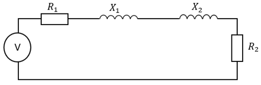
3. Locked‑Rotor Test – Rotor and Stator Leakage Impedances
For the locked‑rotor test, the rotor is mechanically locked so it cannot rotate. A reduced AC voltage is then applied to the stator, and the voltage, current, and total input power are measured. The voltage is adjusted so that the current reaches approximately full‑load current.
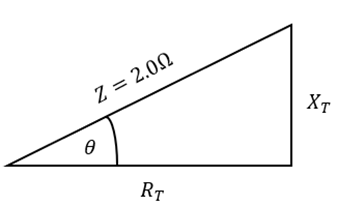
With no rotation, the slip is effectively 1, meaning the rotor operates at standstill frequency. Under this condition, the magnetising branch contributes minimally and can be neglected, allowing the measured impedance to represent the combined stator and rotor leakage impedances:
Since is already known from the DC test, the rotor resistance
can be obtained by simple subtraction. The reactive part determines the combined leakage reactances. The best way to learn how to interpret this test data is to work through an example problem.
Example Induction Motor Parameter Question
A three-phase, star-connected induction motor rated at 415 V and 50 Hz, with a rated winding current of 45 A, was subjected to a series of tests to determine its performance characteristics. During the D.C. test, an applied phase-to-phase voltage of 25 V produced a current of 45 A. In the no-load test, the motor operated at a line voltage of 415 V with a line current of 7.5 A, and the measured three-phase power was 600 W. For the locked-rotor test, the motor was supplied with a line voltage of 70 V, drawing a line current of 35 A, and the recorded three-phase power was 2750 W.
DC Test
No-Load Test
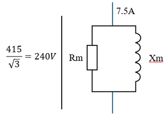
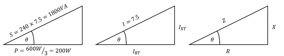
Current components:
Using Ohms Law you can get the following:
Locked Rotor Test
The rotational losses (Rm & Xm) are negligible; therefore the equivalent circuit is as follows: